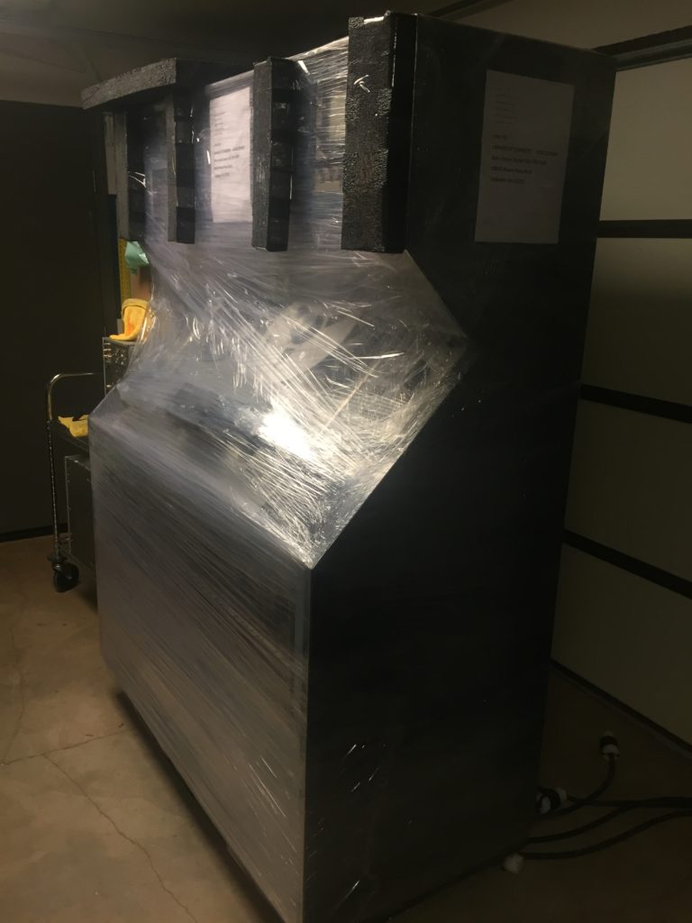
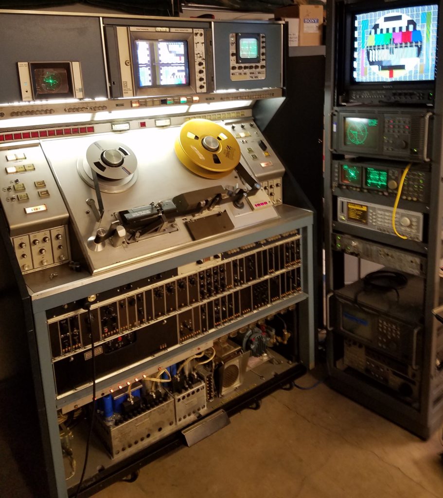
Zinfurbished RCA TR-70C ready to ship to Library of Congress.
The last phase of a multi-year Zinfurbishment has arrived for this RCA TR-70C 2″ Quad television tape recorder:
It shipped Oct. 24, and is on its way back to the customer in an air ride van, ready for useful productivity!
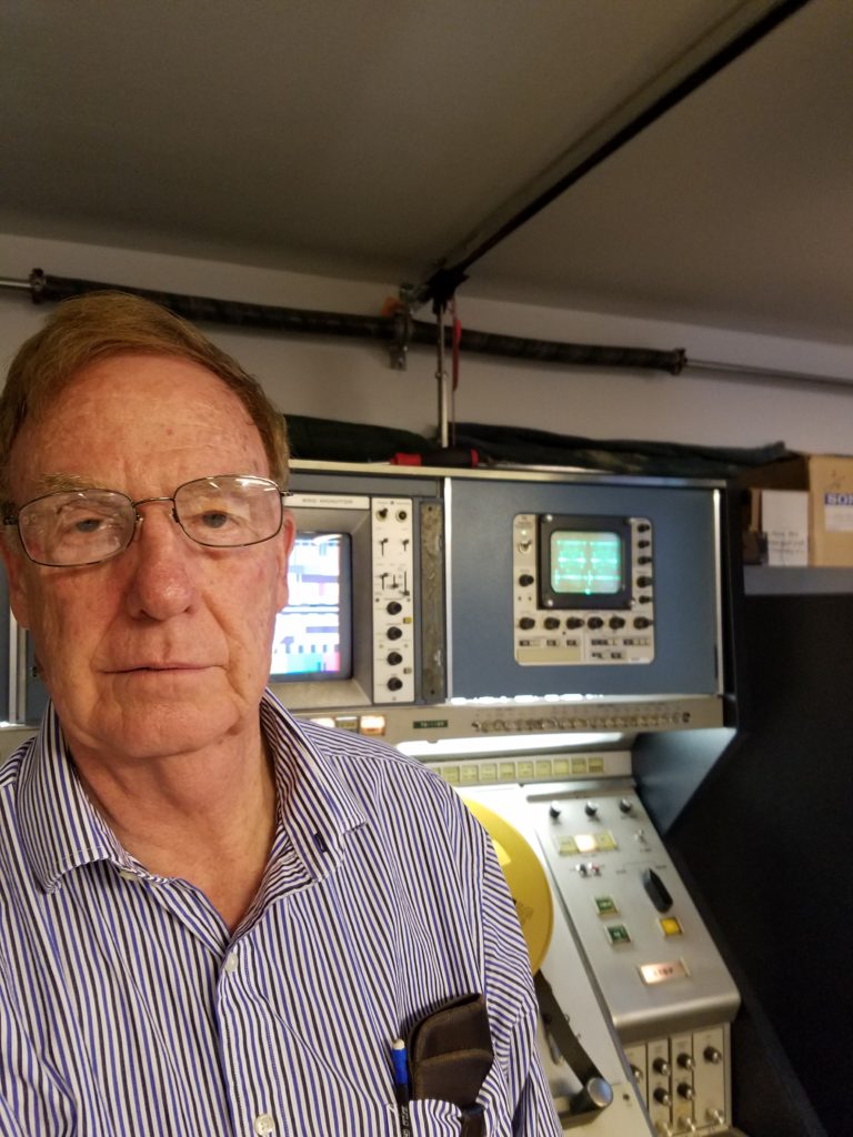
Ken Zin with Zinfurbished RCA TR-70C prior to shipment to Library of Congress
Bringing this aging dinosaur back to life required all the talents Ken Zin could bring to the table, and then some more.
Ken had to play “Dinosaur Detective” to find needed hardware and components.
“The hardest part was to find the three different card extenders,” which place cards out the front of the machine for troubleshooting and adjustment.
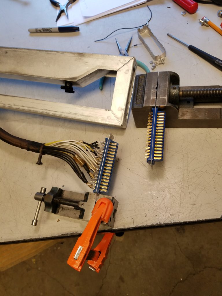
RCA TR-70C Quad Videotape Recorder Card Extender-Replacing bad connector
Ken also had to find connectors to replace damaged ones on one extender, and then unsolder the 32 connections from the bad connector and re-solder them on the new one on the correct pins.
Having multiple extender cards enabled Ken to check signals leaving one board and verify that signal arrived in the same condition at the destination board.
It also let him perform “wiggle checks” on card sockets, connectors and wiring harnesses to see whether there were any continuity issues.
He ran into a situation that led him to believe that there were issues in the wiring harness(es) with either wires or connectors.
RCA’s use of three sizes of pressure-fit, tapered connector pins is a known issue with RCA decks, particularly in mobile units, because things get loose.
In the course of troubleshooting, Ken discovered and addressed a number of issues connected to RCA’s design or manufacturing methods, among them some grounding issues. When corrected, they reduced noise in circuits in ways he could measure and see.
Other repairs and modifications significantly improved quality in other areas, such as this 2T Pulse measurement, which shows just how clean and quickly the playback signal was. More work made it even better.

RCA TR-70C 2T Pulse test signal measured on Tek TM-700 measurement system
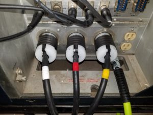
RCA TR-70C Rear power panel with brand-new power cables.
Ken began with the power system, creating three, 30-amp power cables from scratch.
This ensures long-life without safety issues that using 40-year old cables would create.
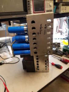
RCA TR-70C-Power Supply with new capacitors being bench-tested before reinstallation in the machine.
The deck’s power supply system was completely Zinfurbished with a number of Zinprovements. Ken added regulation where none existed, and eliminating noise that was carried into video and audio circuits.
The power supply regulation improved servo and signal system performance. The noise elimination significantly improved picture and sound quality, visibly observable on waveform monitors and vectorscopes. The power supply Zinfurbishment also offers more long-term reliability.
Zinfurbishing required extensive reverse-engineering, as the unit arrived without manuals.
Finding manuals required a lot of research time and expense, and made the project take longer.
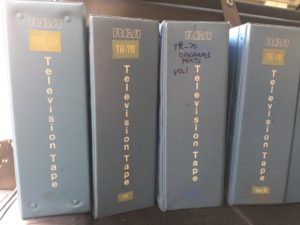
Some manuals were located in Belgium, obtained and shipped to the United States.
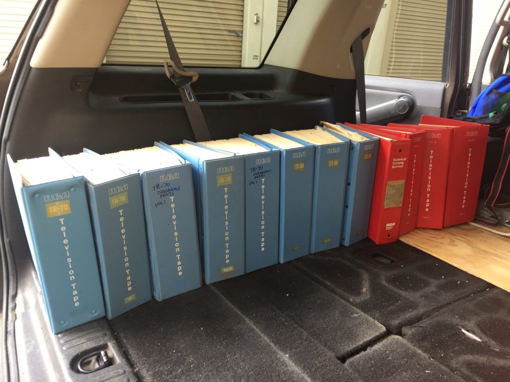
RCA TR-70 and TCR-100 Manuals from the Gary Adams Collection being loaded for transport after donation.
Others, like these, were provided by other engineers who generously offered them in order to preserve the information as they downsized their collections.
RCA TR-70 Manuals from the Gary Adams Collection
Many pages were scanned and OCR’d into searchable text.
That allowed fast, computerized searches to speed up the work. Scanning the schematics at very high resolution made for easy magnification of small sections using a UHD monitor visible across the room.
During the process, Ken made a number of modifications to circuits in order to replace unobtainable components (like germanium transistors) with more modern components.
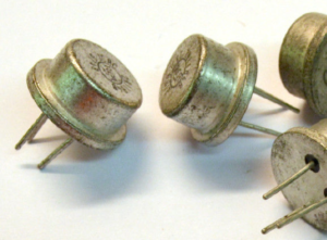
RCA Transistors
Determining what components would work required consulting component specification sheets and books, many of which were acquired for this project, which took time and money. These were also scanned for faster component lookup.
Once the existing components’ technical details were known, Ken could do the math to determine what could be substituted, and what additional components or circuit modifications would be required.
That also required puzzling out why RCA designed some circuits the way they did. In many ways, he says it seemed as though RCA took their late 1950s tube VTR design and transistorized it, but didn’t take advantage of benefits a “solid state” based design could have offered.
The story prompted a parody of a song from “The Music Man”: “Dig a little, fix a little. Dig a little, fix a little. Dig! Dig! Dig! Dig a lot, fix a little more.”
The TR-70C arrived with a Tektronix 650 color monitor. It needed repair and alignment to provide good-looking, stable pictures. At one point, Ken investigated an overbridge modification to enable use of a newer Sony 14″ BVM series monitor, which was deeper than the monochrome or color monitors originally supplied by RCA.
The TR-70C arrived with the original-equipment, RCA blue, Tektronix 529 waveform monitor. “The Tek 529 WFM is tube type,” Ken relates. Finding tubes would be time-consuming. Without a tube-tester, checking tubes for proper operation would be a problem. A tube-based unit would be an ongoing problem to maintain, and a source of un-necessary heat and power draw. RCA supplied late versions of the TR-70C recorders with Tektronix 1480C waveform monitors, a solid-state device except for the CRT and lamps. So Ken went that way.
“I had several full-rack width Tektronix 1480R models, but no compact 1480C types,” Ken says. “I searched for the 1480C, bought five of them to make three of them work, along with using parts from two 1480Rs.”
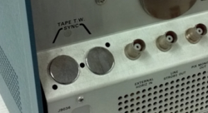
Tektronix 1480C-Rear-Tonewheel Sync option connector holes
But that didn’t enable them to be used with the TR-70C. “I need to recreate the Tektronix option -04, which enables the 1480C to synchronize its scope trace to the RCA’s video head tone wheel to display the off-tape RF signal.”
Part of the servo system, that “tone” is generated as the video headwheel with four heads spins at 14,400 RPM with the heads writing tracks across the tape as it moves from supply reel to takeup reel. Viewing the tone wheel signal on the waveform monitor helps identify tape and machine issues.
“So, I created several circuit board kits to add the option.”
Creating the circuit board kits and refurbishing the waveform monitors had its challenges: “Finding Tektronix part # 151-0492-XX was not easy.” Ken had to find a cross-reference to the common part number—from a guy in Canada—and then find the transistors on-line. There were a few other detours along the way. “I also had to modify the 1480C main board by adding specific parts, removing others and modifying a harness.”
He found that a particular chip being substituted for an “unobtainum” one had a diode in-circuit, where the original did not. “That created problems we had to puzzle out and create a workaround for.”
To verify that everything worked before being installed in the TR-70C, Ken bought several Tektronix test fixtures for the 1480C, “so I wouldn’t have to kill my back while standing on a ladder, poking around inside the 1480C with scope probes with it sticking out from the overbridge.”
On the other side of the overbridge, Ken found that the RCA factory speaker was missing. Replacing it required creating a wooden box to provide quality sound, but would also shield the Tektronix 602 X-Y vectorscope from interference involving the speaker or its permanent magnet. “I used a metal plate sandwiched in between two pieces of wood on the bottom, which avoided interference, yet provided the acoustic chamber we needed for good sound.”
RCA Quad machines have ganged, pushbutton switches for a ton of functions.
It’s difficult to switch functions without the switch-cap on the end of the actuating rod. Since quite a few of these 40-year old clear plastic switch caps were missing, cracked or broken, Ken replaced them. All 63 of them.
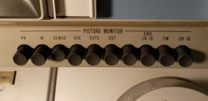
Zinreplacment buttons on RCA TR-70C ganged front-panel switches. These black buttons replaced clear plastic ones more than 40 years old, some of which had cracked, were loose or were missing.
The buttons were measured, and computer drawings made. The caps were manufactured in sets of 66, so three spares were available. It was not cheap to do.
You can see the results: Uniform look and function across the entire machine! And less likelihood that any switch caps will crack or break for the rest of the machine’s life.
Zinfurbishment also eliminated issues found with aging UHF connectors and UHF to BNC adaptors found on the machine.
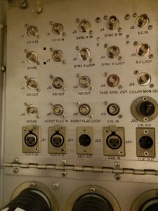
RCA TR-70C with new BNC video connectors replacing aging, trouble-prone UHF connectors on connector panel
RCA’s factory installed UHF style video connectors were replaced with new BNCs. This enables easily connecting necessary wiring with currently standard video connectors
“An aluminum plate was made with “D” holes for the BNCs and tapped 4-40 threaded holes to mount the plate in the same location as the old style UHF connectors,” Ken notes.
XLR audio connectors on the back were inspected, and then cleaned to remove any oxidization.
The existing rubber pinch roller was beyond its useful life, Ken reports, “and could have caused tape damage.”
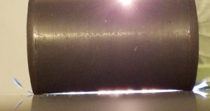
Worn TR-70 Pinch Roller showing light shining through when placed on a flat surface
The roller’s hard surface (improper durometer,) and worn condition, often leads to the use of improper pinch roller pressure to maintain tape movement, and other undesirable conditions. Those include creased tape, bearing wear, jittery capstan movement and greater electronic correction error required to fix the problems.
No original pinch roller specifications or design work was available from which to have new rollers made.
Replacing the rubber pinch roller required careful measurements of the rubber surface, the metal core’s outside and inside diameters, placement and depth of grooves for snap rings, and other parameters.
Computer drawings were made, then used for manufacture of new pinch rollers of the correct durometer (hardness/softness.)
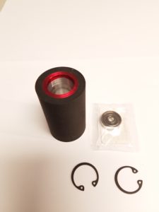
New Zin Replacement RCA TR-70/TR-600 Pinch Roller with Bearing, Internal Snap Ring and Bowed Snap Ring. The Red color indicates which end of the roller the Bowed (wavy) snap ring goes into.
Ken explains the benefits: “The proper durometer allows the tape to slightly indent the rubber surface, and for the fresh rubber surface to be driven by the capstan. That allows the rubber to help drive the tape from its back side, minimizes the chance of slippage and velocity errors, and requires less pressure from the roller assembly to move the tape.
Less pressure is beneficial for the tape, and puts less wear on the capstan and pinch roller bearings over time. They’ll last longer.”
The roller assembly includes new bearings, which ensure smooth running, and minimum interference with tape stability.

Fresh, flat TR-70 Pinch Roller on marble flat surface
And it’s FLAT, as you can see here! No light showing through this roller on the flatness table!
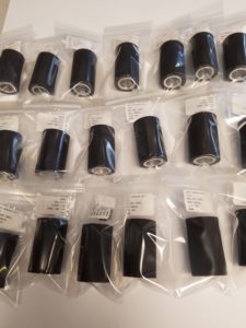
Zin RCA TR-70C Replacement Pinch Rollers, designed and minimum order fabricated to obtain one for a major Zinfurbishment of an RCA TR-70C
A minimum order of 20 was required, so 19 are available for replacing aged and hard pinch rollers on RCA TR-70s and TR-600s RCA Quads. Click here for details and how to order.
These are just a few of the things that were required in order to bring the machine to some semblance of operating.
“Dig a little, fix a little, Dig a little, fix a little,” was quite true when going through the servo and signal circuits.
Some puzzling problems were painstakingly worked through, sometimes with the help of long-time friend, engineer and TBC designer Terry Smith.
Those were identified, with solutions noted and implemented.
RCA TR-70C–Under test using Rohde and Schwarz and Tektronix test signal generators and measurement devices
The results are a machine that—from tests and measurements with Rohde and Schwarz and Tektronix devices—Ken believes more than meets RCA factory specifications, but exceeds them in some ways.
This machine will help the Library of Congress reliably digitize its huge collection of Low Band color and monochrome, High Band color and monochrome NTSC Quad recordings for quite some time.
COMMENTS